September 3rd, 2026
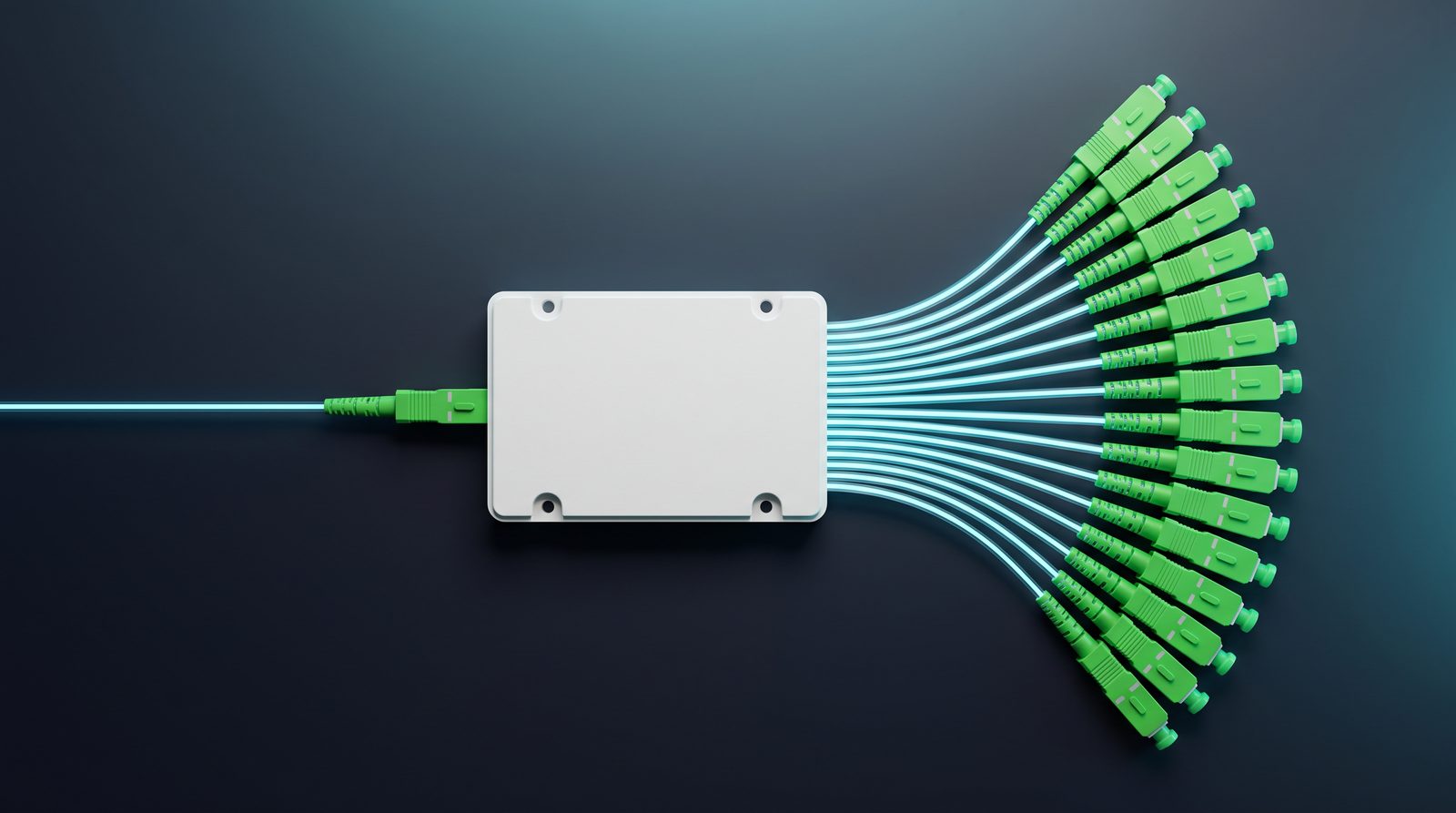
A PLC (Planar Lightwave Circuit) splitter is one of the quiet workhorses of every FTTH and PON network. It takes a single optical signal and divides it evenly across multiple output ports — but “just pick a splitter” does not work in practice. Choose the wrong ratio, polish or package and you either waste optical budget or pay for capability you will never use.
This guide walks through the decisions that actually matter when you buy PLC splitters in volume: split ratio, connector polish, termination style, package format, and how PLC compares with FBT.
The split ratio (1×8, 1×16, 1×32, …) defines how many subscribers or endpoints one feeder fiber can serve. There is no universal “best” ratio — there is only the ratio that fits your split architecture and optical budget.
| Configuration | Typical max. insertion loss* | Typical application |
| 1×2 / 1×4 | ≈ 3.8–7.5 dB | Small FTTH splits, PON for apartments / MDU zones, FTTB |
| 1×8 | ≈ 10.5 dB | Common last-mile split for single homes; balanced cost/loss |
| 1×16 | ≈ 13.5 dB | Centralized split in cabinets / street distribution points |
| 1×32 | ≈ 16.5–17 dB | Large-scale FTTH, central office (OLT) distribution |
| 1×64 | ≈ 20 dB+ | High-density PON; requires careful link-budget design |
*Typical catalog values for a full operating window (1260–1650 nm). Always verify against the manufacturer’s datasheet and your actual link budget.
Practical guidance:
Centralized splitting (one large splitter at the OLT or cabinet, e.g. 1×32 or 1×64) simplifies ODN management and makes testing easier, but consumes the most optical budget per subscriber.
Distributed / cascaded splitting (e.g. a 1×8 at the cabinet feeding 1×8s at the building) is often chosen when the operator wants flexibility in take-up rate.
For most GPON projects, a 1×8 or 1×16 strikes the best balance between fiber savings and manageable insertion loss — which is why they dominate real-world deployments. If you are unsure where to start, our PLC splitter range covers ratios from 1×2 through 1×64.
In PON systems, APC (angled physical contact) is the industry-preferred polish for splitter ports and terminations:
SC/APC — the 8° angled end face minimizes back reflection (return loss ≥ 60 dB), which protects the OLT receiver from reflections in single-wavelength and video-overlay PON systems. If your splitter feeds ONUs directly in a GPON/XGS-PON network, specify APC.
SC/UPC — lower cost and compatible with many datacom links, but its higher reflectance makes it a poor choice for high-split PON with video overlay.
A practical rule: match the polish of the splitter to the polish of the rest of the network, and when in doubt for FTTH, choose SC/APC. The green color code of APC connectors also makes on-site mistakes less likely.
Splitters are delivered in several termination styles, and each suits a different installation:
Bare fiber / steel-tube splitters (0.9 mm or 2.0 mm pigtails, no connectors) are spliced directly into the ODN. They give the cleanest, lowest-loss result and are ideal inside splice closures and ODF trays, but require splicing labor on site.
ABS box splitters with pre-terminated pigtails and adapters arrive ready to plug in — faster installation, easy replacement, and convenient for wall boxes, cabinets and MDU distribution points. This is the most popular format for contractors who need plug-and-play speed.
Rack / LGX cassette and 1U modules mount in OLT racks and 19″ cabinets, keeping high port counts tidy and serviceable in central offices and data centers.
Whichever format you choose, standardize on quality connectors and matching pigtails and patch cords — a good splitter with poor termination loses its advantage.
FBT (fused biconical taper) couplers are older but still useful:
Choose FBT for simple low-count splits (1×2, 1×4) at a single operating window where price is the priority — it is cheaper at these ratios.
Choose PLC for anything from 1×8 upward, or when the splitter must operate across the full 1260–1650 nm range. PLC splits are uniform across all ports regardless of wavelength, which matters for triple-play and future XGS-PON coexistence.
For a more detailed comparison, see our FBT coupler range — but for modern FTTH scale, PLC is the mainstream choice.
When sourcing PLC splitters from a manufacturer, verify these points before committing:
Datasheet honesty — confirm insertion loss, uniformity (±1.0–1.5 dB typical) and operating temperature (–40 °C to +85 °C) are stated per configuration.
Certifications — CE / RoHS compliance and ISO9001 quality systems covering the production line, not just the final product.
End-face and testing — splitters should be 100% tested for insertion loss and return loss before shipment; ask for test reports.
OEM flexibility — a manufacturer that can customize pigtail length, connector type and packaging reduces your on-site work.
Consistency at scale — for projects measured in thousands of units, ask about batch-to-batch uniformity. As a factory manufacturer, Richer controls the full process from splitter fabrication to final assembly — one reason our 1×16 SC/APC PLC splitters and other configurations ship consistently for FTTH and 5G deployments worldwide.
Q: 1×8 or 1×16 — which should a new FTTH rollout use?
A: Both are common. 1×8 is more forgiving of link loss and suits lower-density areas; 1×16 doubles the subscribers per feeder fiber and suits denser urban zones. Model your optical budget, then decide.
Q: Can I mix UPC and APC components in one network?
A: Avoid it — the polishes are incompatible and UPC-to-APC connections create high return loss. Keep the whole path consistent.
Q: What causes splitter failure in the field?
A: Most field failures trace back to poor connector end-face quality or improper handling, not the splitter chip itself. Buy with tested end faces, keep dust caps on until installation, and clean before mating.
Need help selecting the right PLC splitter configuration for your project? Contact Richer for datasheets, samples and factory-direct pricing — our team responds within 24–48 hours.
Be the first to know about new services, special offers and expert tips that can make your everyday life easier.

Copyright © 2025 Qingdao Richer Telecommunications Co.,Ltd All Rights Reserved. Powered by HiCheng .

No.14,Shoufeng Road,Qingdao Free Trade
Zone,266555,Huangdao District,Qingdao City,Shandong Province,China

SUNET: +86 13854278817

